
Introduction
In this project, I am testing the dBi HART Intelligent Transducer from Pulsar Measurement as part of a wireless sensor node system. This sensor is widely used in industrial applications for flow measurement and level monitoring. The goal of this project is to successfully integrate the transducer with an ESP32 microcontroller, enabling wireless data transmission for IoT and automation purposes.
If you’d like to learn more about the sensor, you can check out its official page here.
In this blog, I’ll cover:
- How I wired the sensor to the ESP32.
- The simple code I used to read measurements.
- A video demonstration of testing the system at both maximum and minimum distances.
Wiring
The wiring of the dBi HART sensor with the ESP32 is quite simple. Below is a schematic and step-by-step explanation of how to set it up.
Required Components
- dBi HART Transducer
- ESP32-S3 (or any ESP32 model with ADC support)
- 100-ohm Resistor (for 4-20 mA signal-to-voltage conversion)
- 10V-28V DC Power Supply (for powering the sensor)
Wiring Diagram
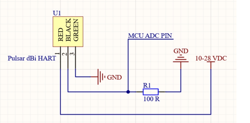
Step-by-Step Instructions
- Power Connection:
- Connect the positive (+) terminal of the 12V-28V power supply to the RED input of the sensor.
- Connect the negative (-) terminal of the power supply to BLACK of the sensor and the ground (GND) of the ESP32.
- Connect GREEN to the ground.
- Signal Conversion:
- Add a 100-ohm resistor between the positive side of the sensor’s BLACK and ground (GND). The signal will be generated from the positive side of the resistor. This converts the 4-20 mA current signal into a voltage range that can be read by the ADC of the ESP32.
- Tap the voltage across the 100-ohm resistor.
- MCU Connection:
- Connect the “high side” of the 100-ohm resistor to an ADC pin on the ESP32 (e.g., GPIO 6).
- Connect the “low side” of the resistor to the GND of the ESP32 (already connected to the power supply GND).
Note: The 4-20 mA signal is converted to a 0.4V to 2.0V range across the 100-ohm resistor (since 4 mA × 100 = 0.4V and 20 mA × 100 = 2V). This voltage range is well within the ESP32 ADC input range (0-3.3V).
Coding
Once the wiring is complete, you’ll need to upload the following code to your ESP32. This simple program reads the ADC pin connected to the 4-20 mA current loop, converts the voltage back to the corresponding current, and prints the value to the serial monitor.
Full Code Example
const adc1_channel_tadcPin= ADC1_CHANNEL_5; // ADC channel to use GPIO 6adc1_config_width(ADC_WIDTH_BIT_12); // Set ADC width to 12 bits
const float resistorValue = 100.0; // 100-ohm resistor to convert 4-20mA to 0.4-2.0V
float current_mA;
void setup() {
Serial.begin(115200); // Initialize Serial Monitor
adc1_config_channel_atten(adcPin, ADC_ATTEN_DB_11); // Set attenuation for ADC channel 6adc1_get_raw(
}
void loop() {
// Read the analog input (12-bit resolution: 0-4095)
int rawValue =adcPin);
// Convert the raw ADC value to a voltage (Assuming 3.3V reference)
float voltage = rawValue * (3.3 / 4095.0);
// Convert the voltage back to the current using Ohm's law (V = IR, so I = V/R)
current_mA = (voltage / resistorValue) * 1000; // Convert to milliamps (mA)
// Print the results
Serial.print("ADC Raw Value: ");
Serial.print(rawValue);
Serial.print(" | Voltage: ");
Serial.print(voltage, 3);
Serial.print(" V | Current: ");
Serial.print(current_mA, 2);
Serial.println(" mA");
delay(1000); // Wait for 1 second before the next reading
}
How It Works
- The ESP32 reads the analog input from the transducer’s signal through the ADC pin (GPIO34 in this case).
- The raw ADC value (0-4095) is converted into a voltage using a simple ratio: Voltage=rawValue×3.34095\text{Voltage} = \frac{\text{rawValue} \times 3.3}{4095}Voltage=4095rawValue×3.3
- Since the 100-ohm resistor is used to convert the 4-20 mA current to a 0.4-2.0V range, the voltage is converted back to the current using Ohm’s law: Current (mA)=VoltageResistor Value×1000\text{Current (mA)} = \frac{\text{Voltage}}{\text{Resistor Value}} \times 1000Current (mA)=Resistor ValueVoltage×1000
- The current is displayed on the serial monitor. This current can be mapped to the transducer’s measured value (e.g., distance or flow rate).
Testing Video
Here’s a video of the testing process, where I show how to measure both maximum and minimum distances with the dBi HART sensor. You’ll see how the current output (4-20 mA) changes as the distance changes.
Key Test Results
- Minimum Distance: Current measured at 4 mA (0.4V) corresponding to the minimum distance.
- Maximum Distance: Current measured at 20 mA (2.0V) corresponding to the maximum distance.
Conclusion
In this project, I successfully interfaced a dBi HART Intelligent Transducer with an ESP32 to create a wireless sensor node. By converting the 4-20 mA signal to a voltage readable by the ESP32’s ADC, I was able to obtain measurements directly from the sensor.
If you’d like to replicate this project, follow the wiring, use the provided code, and remember to check the output using a multimeter before powering the entire system.
If you found this blog helpful, feel free to leave a comment or ask questions. I’m happy to share my experience and help you on your journey to mastering IoT sensors like the dBi HART.
Don’t forget to follow for more project tutorials like this one!
