
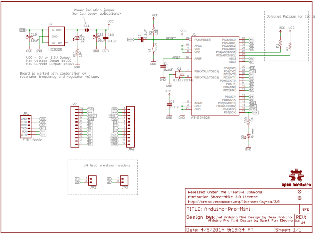
Hi everyone, I’m excited to share my recent achievement with the ATMEGA328P microcontroller. By following the circuit diagram of the Arduino Pro Mini, I successfully created a custom PCB application using the ATMEGA328P chip. Here are the steps and details to help anyone interested in doing the same.
Assumptions
- You have already designed and manufactured your own PCB with the ATMEGA328P chip.
- You have headers for both FTDI and ISP connections.
Getting Started
To begin with, you need to install the MiniCore library, which can be found here: MiniCore Installation Guide.
1. Bootloader Installation
Steps:
- Upload ArduinoISP Sketch:
- Open the Arduino IDE.
- Go to
File > Examples > 11. ArduinoISP > ArduinoISP. - Upload the sketch to your Arduino Uno.
- ISP Connection:
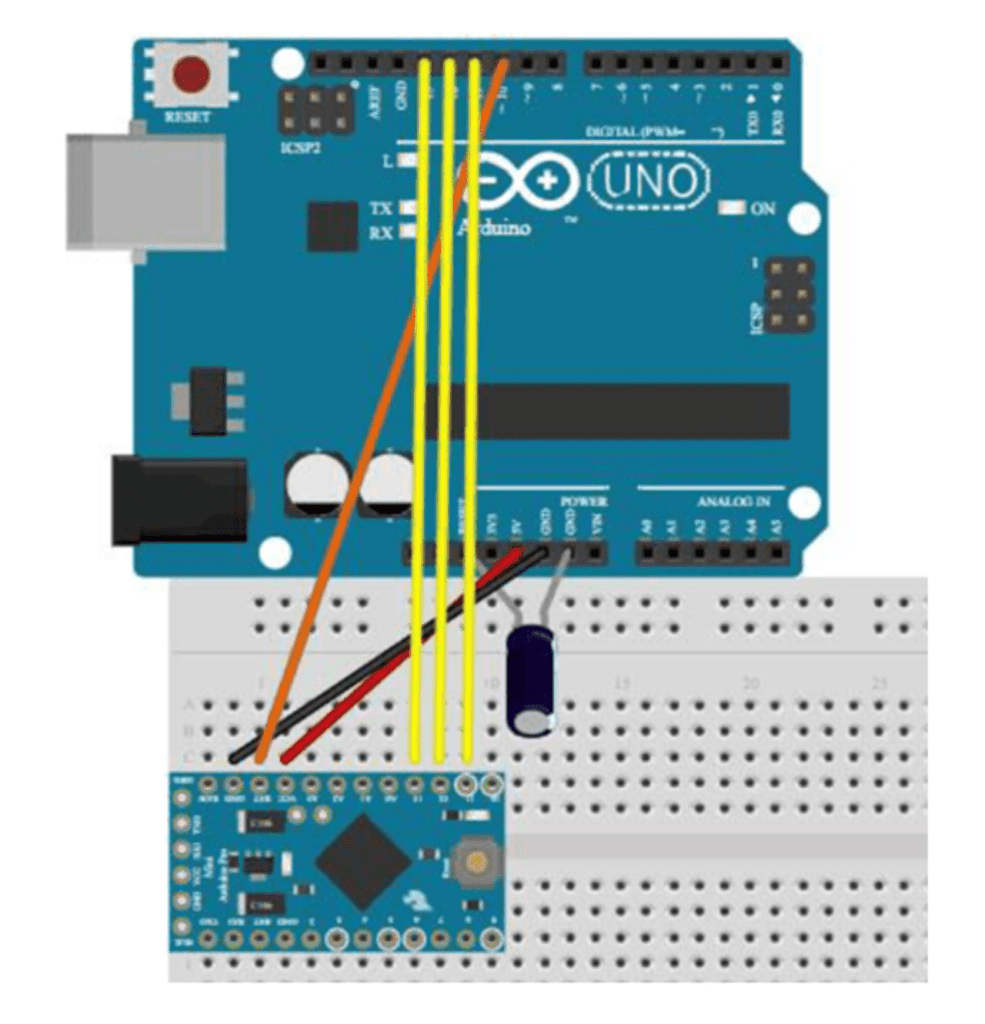
- Connect your ATMEGA328P board to the Arduino Uno using the ISP method. Refer to this article for detailed instructions or follow the connections below:
   ATMEGA328P Chip — Arduino Uno
   GND — GND
   VCC — VCC (3.3V)
   Reset — Pin 10
   MOSI — Pin 11
   MISO — Pin 12
   SCK — Pin 13
Note: Place a 10 uF capacitor between the RESET and GND pins on the Arduino.

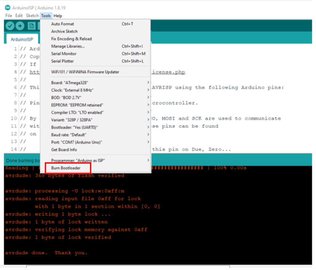
- Burn Bootloader:
- Open
Tools > Board, select MiniCore, and choose your preferred target settings. - Click on
Burn Bootloader.
2. Code Upload
Steps:
- FTDI Connection:
- Disconnect the ISP programmer.
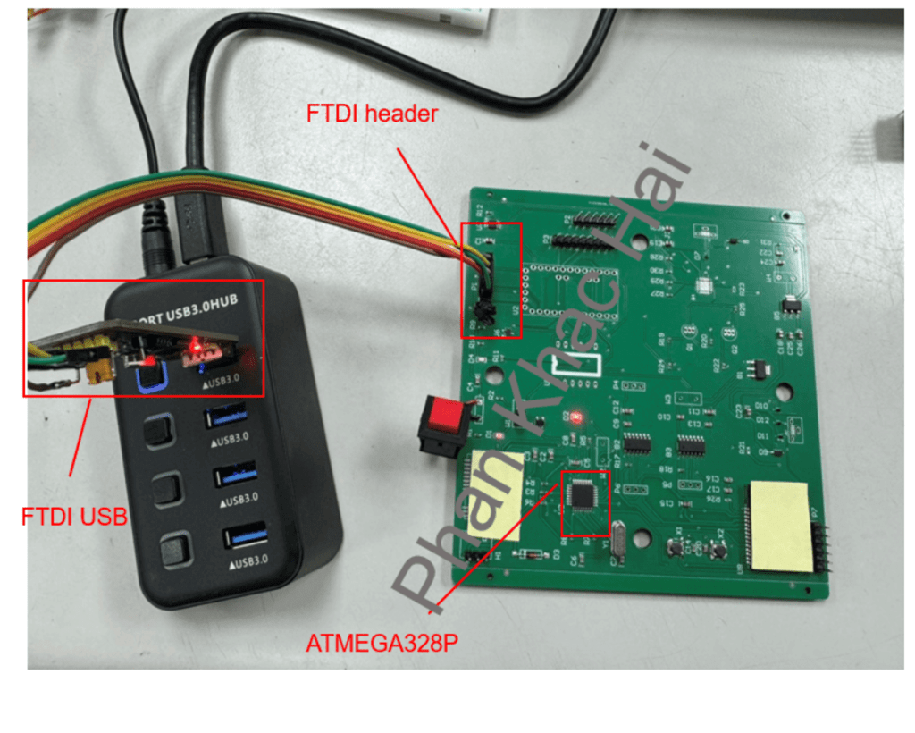
- Connect the FTDI USB to the FTDI header on your ATMEGA328P board. Connections:
   ATMEGA328P Chip — FTDI
   GND — GND
   VCC — VCC (3.3V)
   Reset — DTR
   TXO — RXI
   RXI — TXO

- Upload Code:
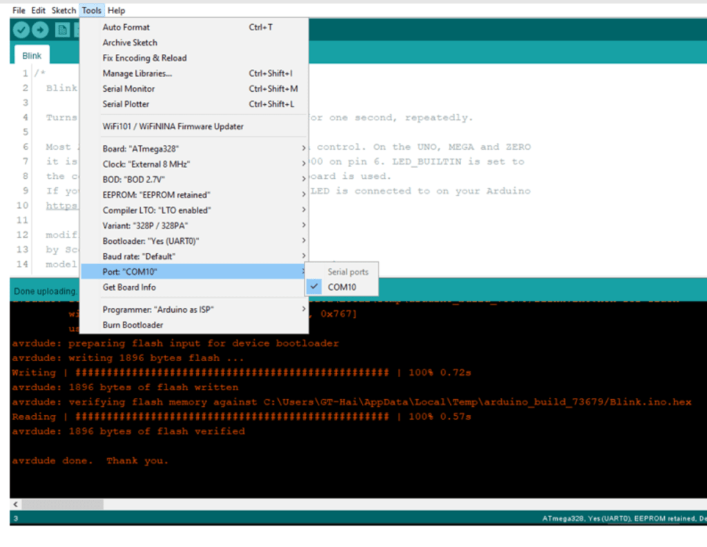
- Select the correct serial port from the
Toolsmenu in the Arduino IDE. - Click the
Uploadbutton. Troubleshooting: - If you encounter a timeout error, ensure that the RX and TX pins are not swapped.
- Verify the auto-reset circuit (including a 100 nF capacitor and a 10k resistor on the reset line).
Conclusion
By following these steps, you should be able to successfully program the ATMEGA328P microcontroller on your custom PCB. This process allows you to leverage the capabilities of the ATMEGA328P chip without needing the full Arduino module, enabling more compact and customized applications.
I hope this guide is helpful to anyone working on similar projects. Enjoy your hardware hacking!
