Introduction
In this article, I’ll guide you through the process of controlling multiple Modbus RTU slave devices using a computer. This involves sending hex commands through a computer terminal to interact with the slave nodes. The objective is to demonstrate the steps involved in computer-controlled Modbus device management.
Hardware Components
The components used in this project include:
- ESP32-S3
- TTL RS485
- ETI sensor
- ADAM 4520 RS232 to RS485 converter
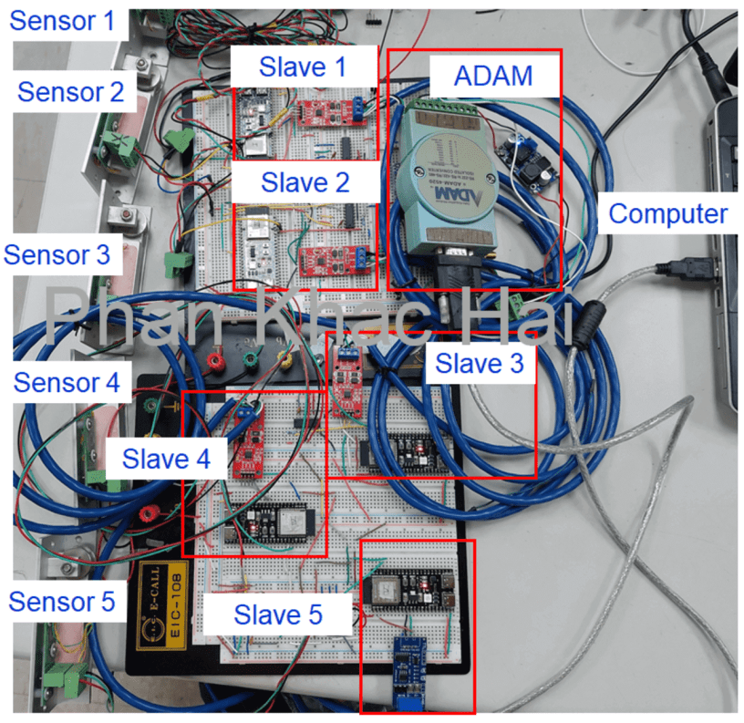
Wiring
Refer to the figure below for the device connections.

Programs
Slave Code
Refer to my previous post for the fundamental concept of the slave program. In this test, I’m sending float type data in a 32-bit 4-byte single-precision floating-point format. Note that I’m using two holding registers starting from 1. Data in float format will be sent with highwords and lowwords.
#include <ModbusRTU.h>


#define RXD1 17

#define TXD1 18

#define SLAVE_ID 1

#define REGN 1

#define ANALOG_PIN A0

#define DELAY_TIME 100


ModbusRTU mb;


void setup() {

  Serial.begin(9600, SERIAL_8N1);

  Serial1.begin(9600, SERIAL_8N1, RXD1, TXD1);

  mb.begin(&Serial1);


  mb.slave(SLAVE_ID);

  mb.addHreg(REGN);

  mb.Hreg(REGN, 100);


  mb.addHreg(REGN + 1);

  mb.Hreg(REGN + 1, 200);

}


void loop() {

  mb.task();


  // Read the analog value from the analog pin

  float eti_read_dig_float = analogRead(ANALOG_PIN);


  // Update the holding registers with the sensor value

  uint32_t temp;

  memcpy(&temp, &eti_read_dig_float, sizeof(uint32_t));


  // Split the 32 bits into high and low words

  uint16_t highWord = static_cast<uint16_t>(temp >> 16);

  uint16_t lowWord = static_cast<uint16_t>(temp & 0xFFFF);


  mb.Hreg(REGN, highWord);

  mb.Hreg(REGN + 1, lowWord);


  delay(DELAY_TIME);

  yield();

}
Slave Modbus Communication Description
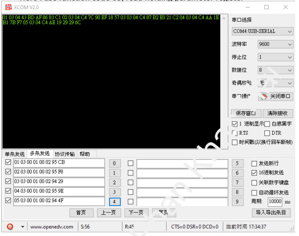
- Command Format: Address + Function Code + Register Address + Data Length + CRC Value Example: 01 03 00 01 00 02 95 CB
- Data Format: Address + Function Code + Register Address + Data + CRC Check Code Example: 01 03 04 43 C0 4C 2D 1B 56
CRC Value
I’ve found a simple method on the Internet using an Excel file for calculating CRC value. If you’re using C#, you can use the provided code to calculate CRC value.
private static ushort Modbus(byte[] buf)

{

    ushort crc = 0xFFFF;

    int len = buf.Length;


    for (int pos = 0; pos < len; pos++)

    {

        crc ^= buf[pos];


        for (int i = 8; i != 0; i--)

        {

            if ((crc & 0x0001) != 0)

            {

                crc >>= 1;

                crc ^= 0xA001;

            }

            else

                crc >>= 1;

        }

    }


    // Swap the bytes of the final CRC value

    return (ushort)((crc >> 8) | (crc << 8));

}
Terminal
From XCOM terminal:
From my Terminal:

Conclusion
Controlling multiple Modbus slave devices through a computer terminal provides a versatile means of managing and interacting with various devices. This article serves as a practical guide to help you understand the steps involved in this process.
